![]()


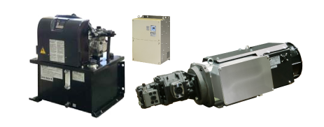
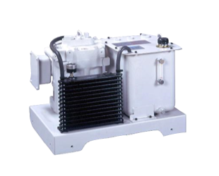
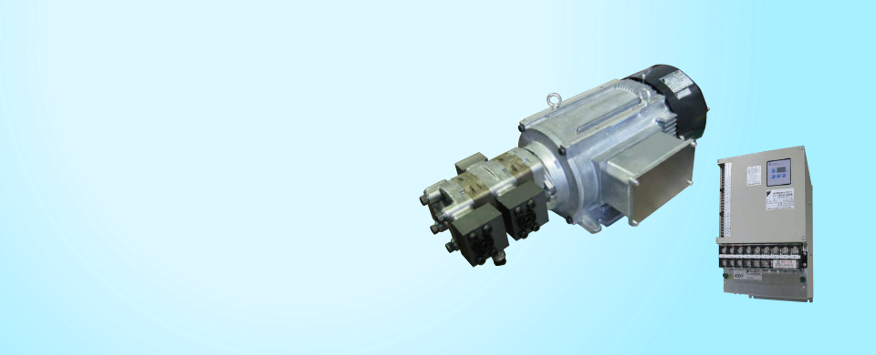
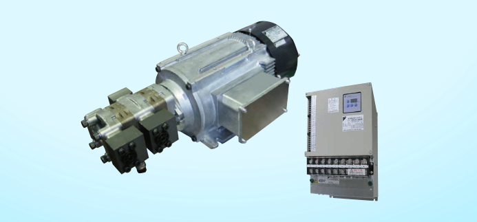
SUPER UNIT
(Analog Command Input, High-Accuracy Type)
Specifications
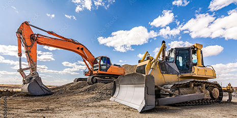
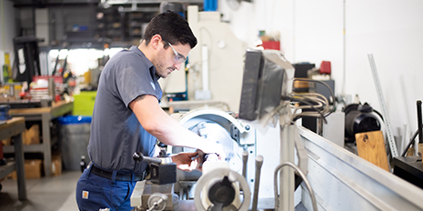
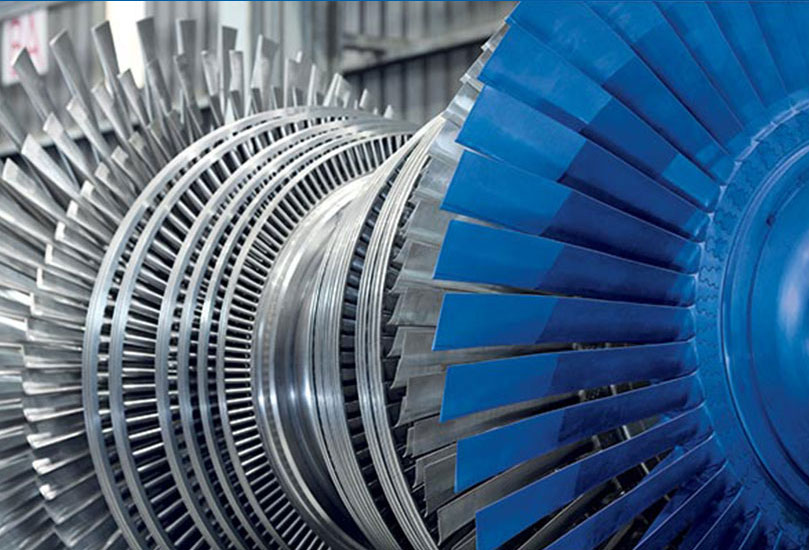
An extensive lineup of pump control systems covering a wide range of applications including presses and industrial machinery.
- Specifications by Product (Single pump 200 V/400 V specifications)
- Specifications by Product (Double pump 200 V/400 V specifications)
- SCpoemcifmicaotnio nSsp beyc Pifriocdautciot (nSsin (g30l eL/ mpiun mto 2p0 02 L0/m0in V, s/in4g0le0/d oVub slep peumcpif, i2c0a0t Vio/4n00s )V specifications)
- Performance Specification
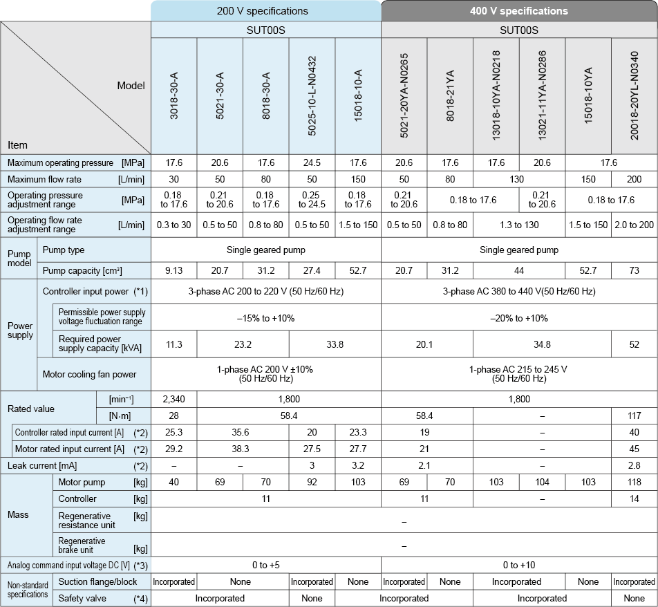
Specifications by Product (Single pump 200 V/400 V specifications)
|
- ※1
- Even if the unit is used within the permissible power voltage fluctuation range, the PQ output characteristics may deteriorate if the power voltage fluctuates to the negative side. Also note that power voltage fluctuation to the positive side may cause alarms, due to overloading of regenerative operation, depending on the operation conditions. You are therefore recommended to use the unit in an environment with limited power voltage fluctuation as far as possible.
- ※2
- Representative values when using a noise filter recommended by DAIKIN. Protection against noise, in accordance with DAIKIN’s recommendations, may be required depending on the operating environment.
- ※3
- With 5 V analog command input voltage specifications, the voltage can be adjusted from 0 to 5 V using parameter VMAX. With 10 V specifications, the voltage can be adjusted from 0 to 10 V, so it can also be operated with 5 V inputs.
- ※4
- With models without a safety valve in the discharge block, incorporate a safety valve in the hydraulic circuit at the machine side. Use the unit with the safety valve set at the maximum operating pressure + 2 MPa.
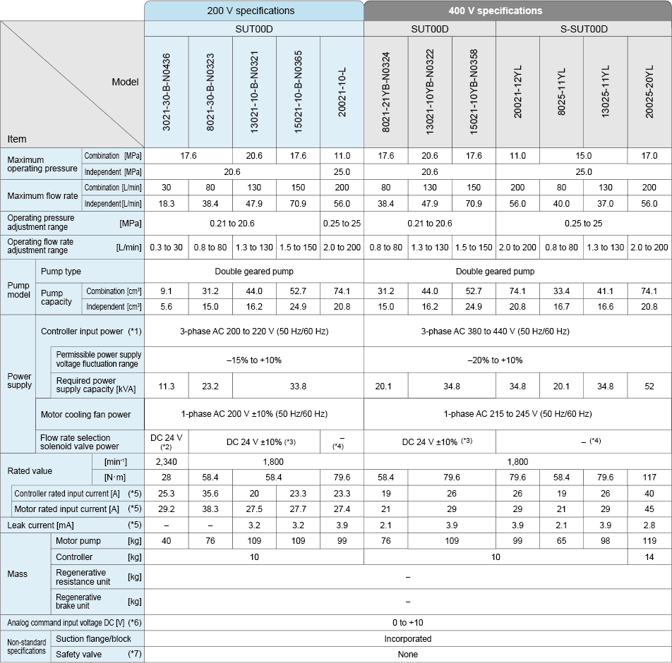
Specifications by Product (Double pump 200 V/400 V specifications)
|
- (*1)
- Even if the unit is used within the permissible power voltage fluctuation range, the PQ output characteristics may deteriorate if the power voltage fluctuates to the negative side. Also note that power voltage fluctuation to the positive side may cause alarms, due to overloading of regenerative operation, depending on the operation conditions. You are therefore recommended to use the unit in an environment with limited power voltage fluctuation as far as possible.
- (*2)
- Solenoid valve model: KSOB-G02-9AP-40-N-H7 (minute signal current type solenoid valve, power supply voltage: DC 24 V ± 10%)
- (*3)
- Solenoid valve model: KSO-G03-20BP-20-EN (power supply voltage: DC 24 V ± 10%)
- (*4)
- Not equipped with a solenoid valve for flow rate selection (Arrange a separately installed type flow rate selection block or provide a flow rate selection mechanism in the hydraulic circuit at the machine side.)
- (*5)
- Representative values when using a noise filter recommended by DAIKIN. Protection against noise, in accordance with DAIKIN’s recommendations, may be required depending on the operating environment.
- (*6)
- With 5 V analog command input voltage specifications, the voltage can be adjusted from 0 to 5 V using parameter VMAX. With 10 V specifications, the voltage can be adjusted from 0 to 10 V, so it can also be operated with 5 V inputs.
- (*7)
- With models without a safety valve in the discharge block, incorporate a safety valve in the hydraulic circuit at the machine side. Use the unit with the safety valve set at the maximum operating pressure + 2 MPa.
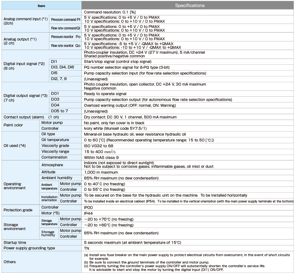
Common Specifications (30 L/min to 200 L/min, single/double pump, 200V/400V specifications)
|
- (*1)
- There are two different voltage specifications: 5 V specifications and 10 V specifications. The PMAX and QMAX settings can be selected using parameters. The input and output voltage settings can be selected using parameter VMAX.
- (*2)
- When incorporating a semiconductor relay in the circuit, select a product with a leak current specification of 1 mA maximum.
- (*3)
- When incorporating a relay in the circuit as a load, take necessary measures against surge or select a surge-resistant product.
- (*4)
- Consult DAIKIN about the use of hydraulic oils other than mineral-oil base type (e.g. hydrous/synthetic) such as water-glycol hydraulic oil.
- (*5)
- The shaft through hole, encoder connector, motor cooling fan and terminal block are excluded.
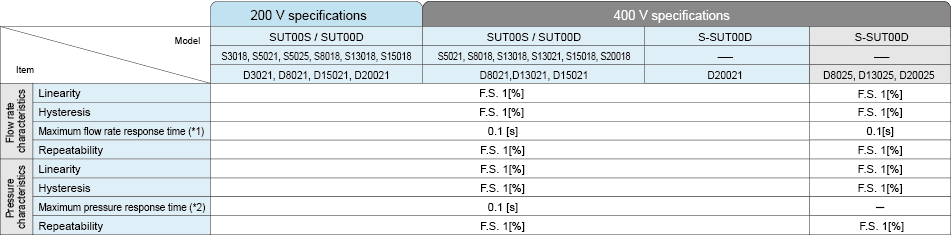
Performance Specification
|
- Note:
- The data given above are the representative performance values, not guaranteed values.
- (*1)
- Time required to reach 95% of the commanded value in response to a command to change the flow rate from 0 to the maximum with no load applied. With S-SUT00S25018 and S-SUT00S30018, it is the time required to reach 90% from 10% under the same condition.
- (*2)
- Time required to reach 95% of the commanded value in response to a command to change the pressure from 0 to the maximum. The volumetric load capacity condition is 2 m of 3/4 high-pressure hose with SUT00S3018 to SUT00S13021, and 2 m of 1B high-pressure hose with SUT00S20018. With S-SUT00S25018 and SUT00S30018, it is the time required to reach 90% from 10% under the same condition. The volumetric load capacity condition is 2 m of 1-1/2B high-pressure hose and a 10 L cylinder with S-SUT00S25018, and 2 m of 1-1/4B high-pressure hose × 2 and a 10 L cylinder with S-SUT00S30018.